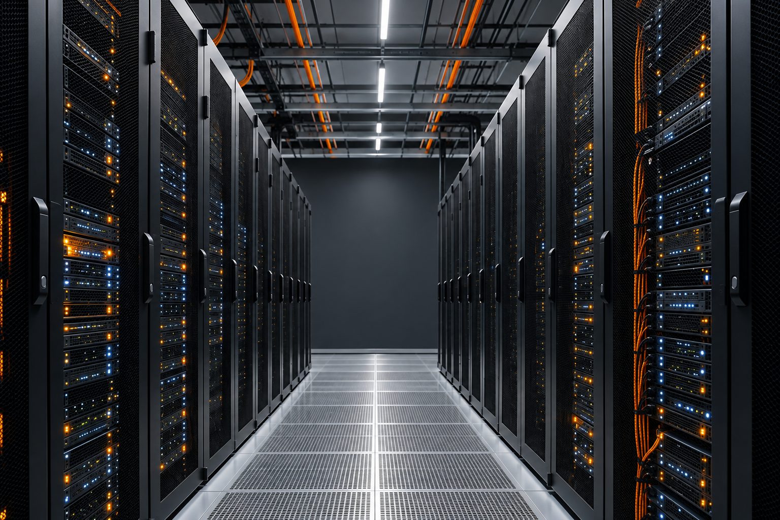
Today, the average data center rack, the kind serving a local bank or hospital, draws around 11 kW.1 Yet a single NVIDIA GB200 NVL72 rack draws upwards of 120 kW2 in the same footprint, and there are no plans for that to be the ceiling. As more compute is crammed into each rack, the industry is heading toward what is widely called the “1MW rack” and beyond. The stark realization is that the industry’s old infrastructure has run out of headroom.
With technology changing this fast to keep up with the industry’s growth, a common theme emerges as the main headwind. The density problem. As more compute is added to these AI racks, they need more power, and as power use goes up, so does the heat coming off them. It’s a simple input-and-output explanation in a world of deep complexity, yet it is one of the largest bottlenecks the industry must address in new data center deployments.
Efficiency might seem like the obvious place to start. More efficiency means less power, right? Well, let’s just say it’s a bit more complicated than that. As systems get better at using power, the savings get spent on more compute rather than disappearing. That is still a big win. Less waste means fewer and smaller supporting systems, a better-managed load, and more compute per square foot, which adds up to smaller data centers and better use of cooling, power and connectivity. But getting there requires the industry to solve three major bottlenecks: power distribution, power conversion, and heat removal. Consider these the three pillars of innovation for addressing the density problem.
Pillar 1: Power Distribution and the Move to 800 VDC
To understand why power distribution comes first, it helps to put a 1MW rack in perspective. Running around the clock, a single 1MW rack uses roughly 8,760 MWh of electricity a year. That’s about as much as 800 average American homes.3 Now picture all of that flowing into a cabinet about the size of a refrigerator. Getting that much power to the rack, and through it, is where today’s architecture starts to break down.
Most AI racks today distribute power internally at about 54 volts DC, a convention that grew out of the Open Compute Project’s 48V rack designs. That works fine at 10 kW, and it’s manageable at 120 kW. At 1MW, it simply isn’t. It comes down to one of the simplest equations in electrical engineering: power equals voltage times current. Hold the power constant, and the lower the voltage, the more current you have to push. At 54V, a 1MW rack would need roughly 18,500 amps. At 800V, the same rack needs about 1,250 amps, almost 15 times less.
Why does that matter? Current is what sizes the copper, and current is what turns into heat on its way to the chip. Losses in a conductor grow with the square of the current, so cutting current by 15x cuts resistive losses by more than 200x for the same amount of copper. By our own back-of-the-envelope math, the busbar feeding a 1MW rack at 54V would need around 250 kg of copper. That’s in the same range as NVIDIA’s estimate of up to 200 kg per rack.4 At 800V, it drops to under 20 kg. That’s the difference between a design that can be built and one that can’t.
That’s why NVIDIA announced in May 2025 that its next generation of “AI factories” will move to an 800 VDC architecture, starting in 2027 alongside its Kyber rack platform.4 The hyperscalers are on a parallel track. Meta, Microsoft and Google have been working through the Open Compute Project on a ±400 VDC design known as Mt. Diablo. It moves power conversion out of the compute rack and into a dedicated “sidecar” power rack, so more of the compute rack is left for compute.5
The story doesn’t end at the rack, though. Compared with a conventional 480 VAC facility, the copper savings on the main feeders are more modest. A DC feeder runs on two conductors instead of three or four, which trims roughly a third of the copper, conduit and labor. The bigger prize is the number of times power gets converted. A traditional facility changes power from one form to another four or more times between the utility and the chip:
- at the transformer
- at the UPS, which converts AC to DC and back to AC
- at the PDU
- and finally at the server power supply
A little is lost at every step. An 800 VDC architecture converts once, close to the source, and stays DC until it reaches the board. A typical AC chain lands near 90% end-to-end efficiency, while an 800 VDC chain lands closer to 95%. That’s consistent with NVIDIA’s claim of up to a 5% improvement.4 On a single 1MW rack, that’s roughly 60 kW that never becomes waste heat. That’s about $30,000 a year in electricity at $70/MWh, before counting the cooling you no longer have to run to remove that heat. Across a 100 MW campus, it adds up to around $3 million a year.6 And as we said earlier, that power doesn’t disappear. It goes back to compute.
Of course, it isn’t a free lunch. AC current crosses zero 120 times a second, which helps extinguish an electrical arc. DC never does, so faults are harder to interrupt. Moving to 800 VDC means new protection equipment, such as solid-state circuit breakers, updated codes and standards, and technicians trained to work safely on high-voltage DC. The supply chain is still young, and many early deployments will be hybrids that run DC to the rack while the rest of the facility stays on AC.
That raises the obvious next question: if the rack wants 800 VDC, where does it come from?
Pillar 2: Power Conversion and the Solid-State Transformer
Today, power reaches the rack through a long chain of equipment: a large iron-core transformer steps utility power down, and then switchgear, UPS systems and PDUs convert it again and again along the way. The solid-state transformer (SST) replaces much of that chain with power electronics, converting medium-voltage AC from the grid directly to 800 VDC in a single, compact unit. NVIDIA and its partners are evaluating SSTs as one way to supply their 800 VDC architecture.4
The appeal is clear. SSTs switch at high frequency, and the magnetic components in a transformer shrink as frequency rises, so SSTs are dramatically smaller and lighter than conventional transformers. Power can also flow both ways, which means batteries and on-site generation can connect directly to the DC bus. Just as important, SSTs are built on semiconductor supply chains rather than the specialized electrical steel behind conventional transformers. That matters at a time when U.S. transformer supply has fallen well short of demand, with lead times often measured in years.
The technology still has some growing up to do. Most SST designs today accept medium-voltage input up to 13.8 kV, a common distribution voltage, but large data center campuses increasingly take power at 34.5 kV. Until SSTs can connect at that level, operators still need a conventional transformer upstream to step 34.5 kV down to 13.8 kV, giving back part of the benefit. The industry is targeting 34.5 kV-rated SSTs within roughly the next year, which would let an SST connect straight to a campus’s main power system.
Manufacturing is the other hurdle. Conventional AC transformers have a century of field history, established standards and factories around the world. SSTs have none of that yet. Production is still limited, long-term reliability at data center scale is still being proven, and cost per kW remains higher than conventional equipment. For developers and investors, that means early SST deployments will carry more technical and schedule risk than the AC equipment they replace.
Even so, the direction is set. A single unit that turns grid power into 800 VDC removes conversion steps, frees floor space, and sidesteps one of the tightest supply chains in the industry. Of course, delivering all that power efficiently only solves half the problem, which brings us to the third pillar: heat removal.
Pillar 3: Heat Removal and the Push to Warm-Water Liquid Cooling
Every watt delivered to the chip eventually becomes heat, and at these densities, air simply can’t keep up. The industry’s answer is direct-to-chip (D2C) liquid cooling. Cold plates sit directly on the GPUs and CPUs, and coolant carries the heat to a coolant distribution unit (CDU), which hands it off to the facility’s water loop to be rejected outside. AMD’s Helios rack, for example, packs 72 liquid-cooled GPUs,7 and Schneider Electric’s reference design for it supports up to 246 kW per rack.8
The bigger shift is how warm that coolant is allowed to run. ASHRAE now classifies liquid-cooled systems by the temperature of the coolant supplied to the IT equipment, from S30 up to S50. At S45 (45 °C, or 113 °F) and above, a facility can reject heat with cooling towers or dry coolers alone, with no mechanical chillers.9 NVIDIA is pushing hard in this direction. Its Rubin-generation systems accept coolant at up to 45 °C, warmer than a hot tub, and send it back out at around 55 °C.10 The payoff is significant.
- Water. NVIDIA says its reference design cuts water consumption from roughly 2.6 million gallons per megawatt per year to near zero.10
- Cost. Each 1 °C increase in supply temperature cuts cooling costs by about 4%. For a 50 MW facility, NVIDIA estimates savings of more than $4 million a year in energy and water.10
- Efficiency. Schneider Electric’s reference design for AMD Helios targets a PUE as low as 1.12,8 compared with an industry average of 1.52.11
Even “fully liquid-cooled” isn’t quite fully liquid-cooled, though. Schneider’s design removes up to 84% of the heat through liquid. The rest still has to be handled by air, so these facilities will be hybrids for the foreseeable future.8
Warm water also creates a new problem: you can’t safely touch it. Under IEC 62368-1, the safety standard for IT equipment, a metal surface a person may hold for more than a minute should stay at or below 48 °C.12 With supply at 45 °C and return near 55 °C, the return manifolds, hoses, quick-disconnects and CDU piping can run above that limit. Technicians swapping a tray or servicing a manifold are now working around surfaces that today’s safety standards treat as burn hazards. That means:
- insulated or guarded piping
- clear labeling
- gloves and other protective equipment
- updated service procedures, possibly including cool-down time before work
None of this was a concern in an air-cooled hall, and the industry’s safety standards haven’t fully caught up.
Warm-water cooling is still the clear path forward. It removes the chiller plant, drastically reduces water use, and puts the heat at a temperature high enough to be reused. But like 800 VDC and the solid-state transformer, it trades one set of problems for another. The winners will be the operators and developers who plan for those trade-offs from the start, not the ones who discover them during commissioning.
Conclusion: Planning for the Density Era
The typical data center rack still draws around 11 kW. Yet the industry is now planning for racks that draw 1MW, use as much electricity as 800 homes, and rely on coolant warmer than a hot tub. The density problem is not going away. It is accelerating.
The path forward is becoming clear.
- 800 VDC distribution delivers megawatt-scale power to the rack without prohibitive copper and conversion losses.
- Solid-state transformers shorten the chain between the grid and the chip and reduce reliance on a strained transformer supply chain.
- Warm-water liquid cooling removes heat efficiently while sharply reducing chiller and water demand.
None of these technologies solves the problem on its own, and each brings new challenges: DC fault protection, SST maturity and manufacturing scale, and touch-safety limits on high-temperature equipment. The projects that succeed will be the ones that plan for all three together, from the start.
Where Continuum Partners Comes In
At Continuum Partners, we treat energy as infrastructure, as a commodity and as a risk to be managed. Our team brings more than 150 years of combined experience across energy markets and development.
As energy advisors, we go well beyond procurement. We use both physical power resources and the financial markets to secure the most competitive cost of power for our clients. We manage load and price risk through hedging, optimize collateral, and identify financial opportunities that turn energy from a fixed cost into a strategic asset. Our team is native to the generation space. We evaluate on-site and behind-the-meter generation, including the spark spread, the margin between the cost of fuel and the value of the power it produces. That lets clients decide when to self-generate, when to buy from the grid, and when there is value in selling back.
As project developers, we identify and develop large-scale energy campuses from 5 MW to multiple gigawatts. We coordinate land acquisition, grid interconnection, permitting and infrastructure planning. Our master-planned sites are designed for phased delivery, on-grid and off-grid power options, and the density these technologies demand: medium-voltage service, substation headroom, space for heat rejection, and a clear path to 800 VDC and warm-water cooling.
Few firms see both sides: the market behind the meter and the site in front of it. That combined view is what keeps our clients ahead of the curve.
The 1MW rack is no longer a question of if, but where. The sites that are ready for it will define the next generation of AI infrastructure.
Sources
- Uptime Institute, Uptime Institute 16th Annual 2026 Global Data Center Survey (press release, July 28, 2026).
- Vertiv, Vertiv codevelops with NVIDIA complete power and cooling blueprint for NVIDIA GB200 NVL72 platform (press release, Oct. 15, 2024).
- U.S. Energy Information Administration, How much electricity does an American home use?
- NVIDIA Technical Blog, NVIDIA 800 V HVDC Architecture Will Power the Next Generation of AI Factories (May 2025).
- Open Compute Project, Mt. Diablo ±400 VDC disaggregated power rack (Meta, Microsoft, Google).
- Methodology note: Continuum Partners analysis. Assumptions: 1MW IT load, 80% load factor, $70/MWh; AC chain ≈89.9% end-to-end (transformer 99%, double-conversion UPS 96%, PDU 98.5%, server PSU 96%); 800 VDC chain ≈95.1% (transformer 99%, rectifier 98%, in-rack DC-DC 98%).
- AMD Newsroom, AAI 2026: AMD Launches AMD Helios Rackscale Solution for Frontier AI (July 23, 2026).
- Schneider Electric, Schneider Electric and AMD Release First Helios Platform Reference Design to Accelerate AI Factory Deployment (press release, July 24, 2026).
- ASHRAE TC 9.9, Technology Cooling System supply temperature classes S30–S50 (2024).
- NVIDIA Blog, Hotter Than a Hot Tub: The 45°C Breakthrough to Cool AI’s Biggest Machines (June 22, 2026).
- Uptime Intelligence, The growing PUE advantage of larger data centers (Aug. 6, 2026).
- IEC 62368-1, Audio/video, information and communication technology equipment, safety requirements; touch temperature limits (TS1).
 Contact Us


